Lego Technic Power Function motors are nice and easy to hack for robotics projects – in large part because they come with a built-in gearbox so you get nice amounts of torque at low speeds right out of the box.
Here’s a quick breakdown of what you need to know. The tl;dr is that you apply a 9V PWM signal to the two inner cores of the ribbon cable. The outer two cores are not connected.
I’m using the M Series 8883 motor but there are plenty of alternative choices available. I’ve not tried them but I would assume they all use the same pin-outs.
The motor is supplied attached by a four-way ribbon cable to a lego electrical connector:
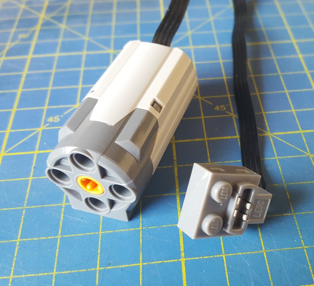
You can either snip this cable in the middle and solder the individual cores or you can sacrifice a simple lego PF extension cable instead and leave your motor assembly intact.
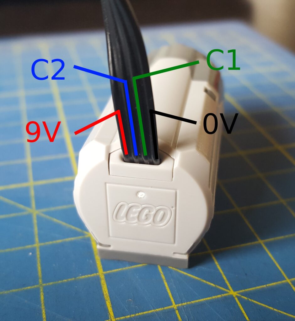
The Lego PF system uses a standard pin-out system across all the products but note that for our purposes here we only need the C1 and C2 lines (the 0V and 9V lines are not connected inside the motor).
Here’s a photo of the motor end showing the pin-outs:
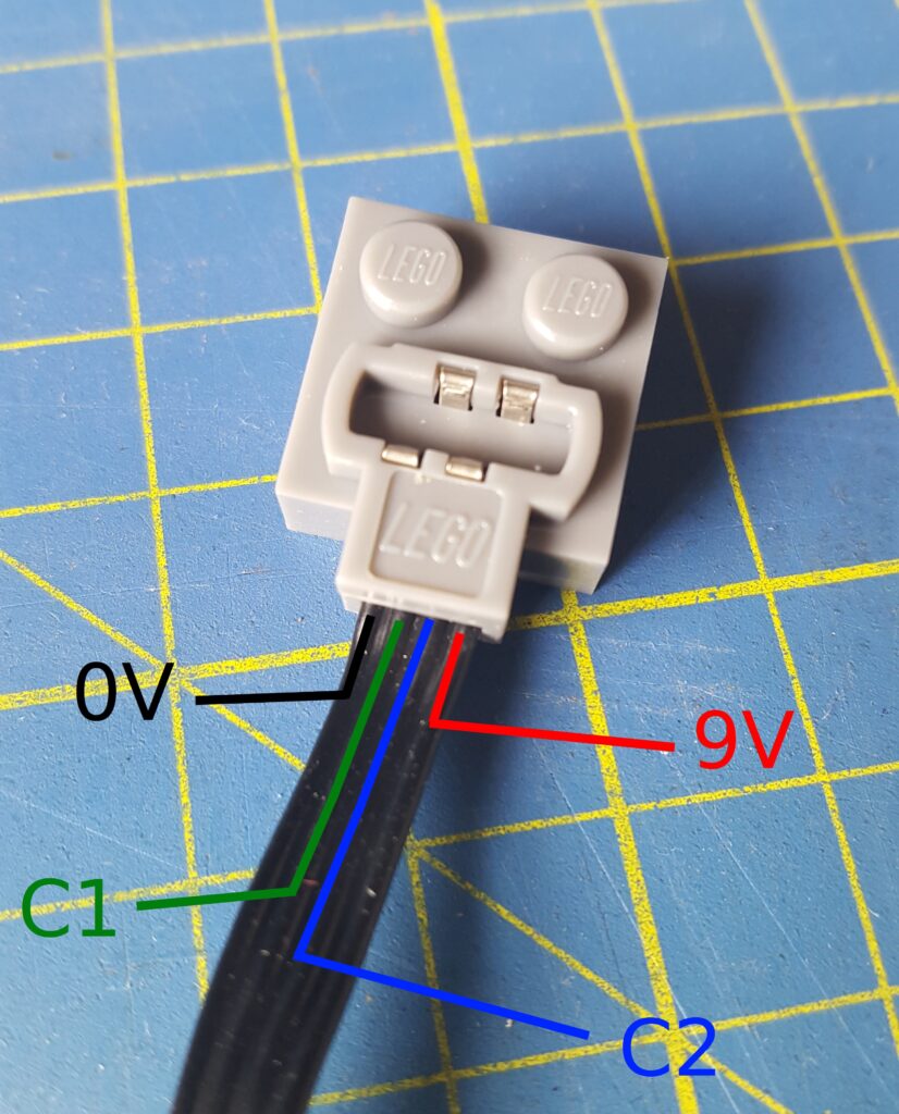
And here’s the pin-outs for the connector end. Which you might need if you’ve just cut your motor cable in half without making a note of the cable orientation…
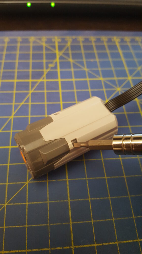
If you’re interested in the internals, undo the small crosshead screw
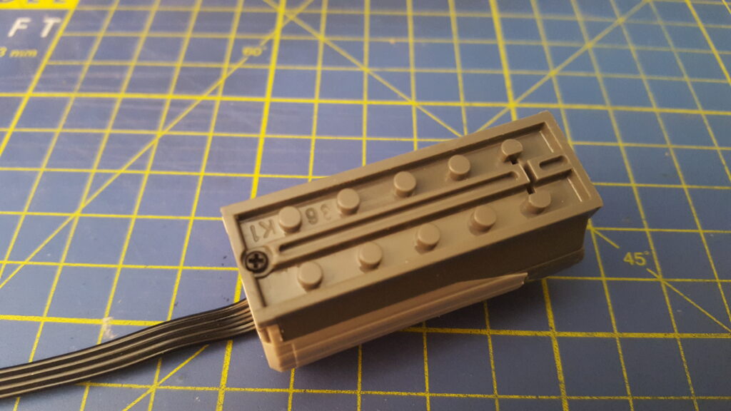
then prise off the housing using a small flat-bladed screwdriver trying not to stab your fingers and thumbs in the process
Once that’s off you can pull off the gearbox (which itself comes apart very easily to reveal a set of three planetary gears):
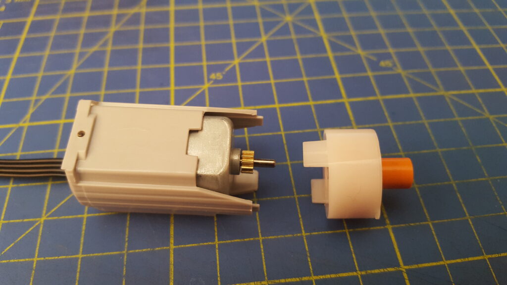
Finally you can slide off the inner housing to reveal the motor itself and the small smoothing capacitor.
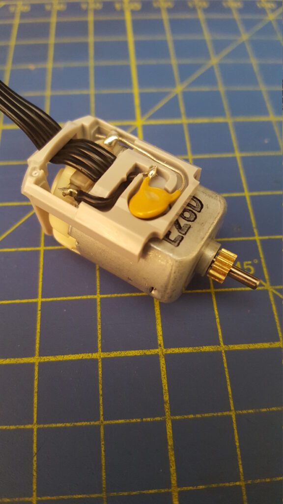
You can then see that the outer two cores (0V and 9V) are not connected to the motor internally. So, you control the motor by putting 9v on C1 and 0v on C2 to spin the motor anti-clockwise as seen from the outside, or alternatively put 0v on C1 and 9v on C2 to spin it clockwise as seen from the outside. To control the speed, apply a 0 to 9V PWM signal of the required duty cycle on the logic high control line. In terms of current draw, my M series motor pulls about 70mA when free running and up to about 500mA when I really load it hard. Bottom line – you need a controller circuit to run this, you can’t just hook it up to a micro-controller’s digital out lines.
Leave a Reply